

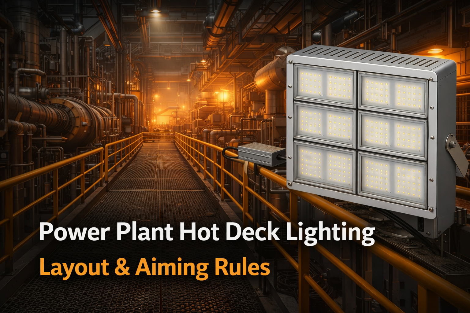
Power plant hot decks—boiler decks, turbine decks, mezzanines, and catwalk networks—are deceptively difficult to light well. The geometry is narrow and complex, surfaces are reflective, hot air plumes create localized temperature spikes, and maintenance access is expensive.
That’s why many upgrades fail when they rely on “same wattage replacement” instead of layout rules and aiming discipline. This guide gives practical power plant hot deck lighting: layout tips and aiming rules for high temperature environments, so you can achieve safer inspection visibility with fewer glare issues and fewer maintenance interventions.
For the full high-temperature framework (Ta rating, radiant heat, driver strategy), read High Temperature LED Lighting – Complete Guide.
1) How do you light power plant catwalks and inspection points safely?
In power plants, you are rarely lighting an open floor. You are lighting:
- narrow catwalks with handrails
- inspection points (valves, gauges, panels)
- ladder landings and stair transitions
- equipment service corridors
- turbine hall access paths
Safe lighting means three things:
1) Uniform visibility along the walking path (no dark gaps)
2) Low glare in normal sightlines
3) Reliable operation at elevated Ta (because the deck is hot)
1.1 Start from tasks, not fixture wattage
Define your target zones:
- “walking plane” on catwalk grating (visibility of trip hazards)
- “vertical plane” on gauges and valve tags
- “inspection zones” around panels and service points
If you don’t define the task, suppliers will quote based on wattage and lumens. That is the fastest path to glare and poor uniformity.
If you want the deeper logic, see Why “Same Wattage Replacement” Fails in High Temperature Zones.
1.2 Choose temperature class with margin (Ta at mounting point)
Hot decks often run in 70–95°C air near structure height, and hotter in plume paths. Select a fixture class based on measured Ta at the mounting point—not a floor-level reading.
A practical baseline:
- 80°C / 176°F class: warmer areas with limited plume exposure
- 100°C / 212°F class: many boiler/turbine deck applications
- 150°C / 302°F class: plume-adjacent or radiant-loaded positions (remote driver often recommended)
To browse the overall product family path, use Industrial Light.
2) Which beam angles reduce glare on reflective equipment surfaces?
Glare is one of the biggest reasons power plant upgrades “feel worse” even if the average lux is higher. Reflective pipes, steel housings, and polished equipment surfaces create strong specular reflections.
The goal is to control where peak intensity goes.
2.1 Practical beam angle rules (catwalk geometry)
As a rule of thumb:
- Narrow catwalks: avoid extremely wide beams that spray into sightlines
- Medium beam angles often provide better control and uniformity without harsh hotspots
- Very narrow beams can work at high mounting heights, but they require careful aiming
Use Flood Light Design Guide as your optics reference for beam angle and aiming basics.
2.2 Aiming rules that reduce glare immediately
1) Aim away from the normal walking sightline.
Peak intensity should not point down the catwalk into the eyes of an approaching operator.
2) Use cross-aiming instead of straight aiming.
Where geometry allows, aim fixtures slightly across the walkway rather than straight down the length. This reduces “runway glare.”
3) Keep tilt limits.
In many hot deck layouts, small aiming changes cause large glare differences. Set an aiming limit (e.g., “tilt ≤ X°”) and lock the bracket to prevent drift from vibration.
4) Place fixtures to avoid direct reflections.
Avoid placing fixtures where they reflect directly off large pipes or shiny equipment into common sightlines.
3) When is remote driver placement recommended in power plants?
Remote driver placement is recommended when any of the following are true:
3.1 Ta at the fixture location approaches the driver’s comfort zone
If the mounting point runs close to 100°C during normal operation, integrated drivers often operate under high stress. Even if the LED array survives, the driver can fail early.
3.2 The fixture sits in a hot plume path
Plumes create localized spikes that are not captured by “average room temperature.” Moving drivers to a cooler location often produces the biggest reliability gain.
3.3 Maintenance access is difficult or requires downtime windows
If accessing the fixture requires shutdown procedures or heavy access equipment, remote drivers can reduce maintenance risk and time.
In many plants, remote driver strategy is most common in 150°C / 302°F class environments and plume-adjacent installations. If you’re building your 150°C path, see High Temp 150°C Lights.
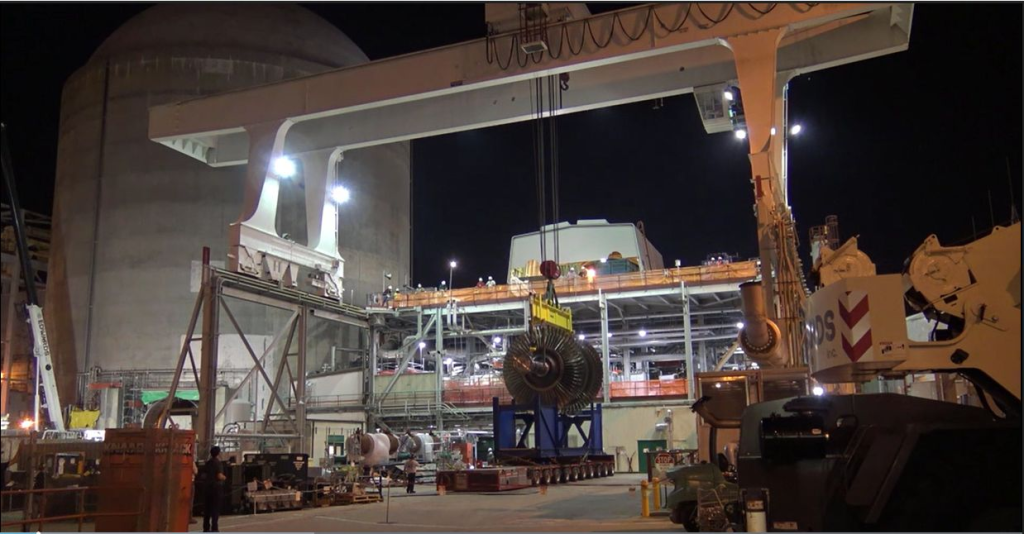
4) Layout tips for hot decks (what works in real plants)
4.1 Light the path first, then the equipment
Start with catwalk continuity:
- consistent spacing
- overlap beams to avoid dark gaps
- prioritize min/avg uniformity rather than peak lux
Then add targeted lighting for:
- gauge faces
- valve banks
- service panels
- ladder landings
4.2 Avoid “one fixture does everything”
Hot deck lighting usually performs best as two layers:
- path lighting layer (uniform, low glare)
- task/inspection layer (more directed, controlled aiming)
4.3 Require IES files if you want predictable results
IES photometrics prevent trial-and-error. If suppliers cannot provide IES files, layout accuracy will suffer.
4.4 Account for dust and cleaning intervals
Dust on heat sinks reduces cooling and increases internal temperatures, which reduces reliability. Dust on lenses reduces delivered lux on the walking plane. Plan cleaning intervals and use fixtures suitable for dusty environments.
For ingress and durability basics, see IP and IK Ratings Explained.
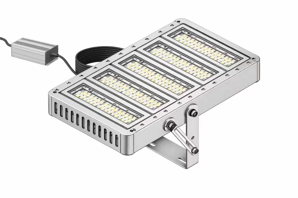
6) REITA experience
Turbine deck catwalk: glare reduction + reliability
A facility needed improved visibility on turbine deck access routes while reducing glare and minimizing maintenance interventions. The previous retrofit created bright points and dark gaps, and glare was noticeable on reflective equipment surfaces.
The solution focused on:
- a layout built around catwalk continuity and uniformity,
- aiming rules that moved peak intensity out of normal sightlines,
- optics selected for the mounting height and walkway width,
- and driver strategy suited to plume-adjacent areas.
Result: better inspection visibility with fewer glare complaints and improved service stability.
For project-specific recommendations, start here: Contact REITA.
7) Quick FAQ
How do you light power plant catwalks and inspection points safely?
Use a two-layer approach: uniform low-glare path lighting for catwalk continuity and targeted task lighting for inspection points. Specify lux targets and uniformity, not wattage.
Which beam angles reduce glare on reflective equipment surfaces?
Beam angles that control peak intensity and avoid spraying into sightlines reduce glare. Combine correct beam angles with aiming rules: cross-aiming, tilt limits, and placement that avoids direct reflections off equipment.
When is remote driver placement recommended in power plants?
Remote drivers are recommended when Ta is high (near 100°C), fixtures sit in plume paths, or maintenance access is costly. Moving electronics to cooler locations often improves reliability dramatically.
If you share photos, mounting height, measured Ta (avg/peak), and plume/radiant exposure notes, we can recommend optics, spacing, and driver strategy for your hot deck.

